where is the 3d objects toolbar in open office draw
This is Chapter 7 of the OpenOffice.org 3 Draw Guide, produced by the OOoAuthors group. A PDF of this chapter is available from this wiki folio.
Contents
- i Creating 3D bodies
- 1.1 Variation one: Extrusion
- 1.2 Variation 2: Trunk rotation
- 1.three Variation 3: Using ready-made objects
- 2 3D scenes
- 3 Producing 3D shapes
- three.1 Variation 4: Extrusion of shapes
- iii.2 Variation five: Fontwork
- 4 Editing 3D objects
- 4.1 Rotating 3D objects
- 4.ane.1 Process for 3D bodies
- iv.1.2 Procedure for 3D shapes
- 4.2 3D settings for 3D bodies
- 4.2.1 3D Effects dialog — general buttons
- four.ii.2 3D Effects - Geometry
- four.2.3 3D Effects - Shading
- 4.2.4 3D Furnishings - Illumination
- 4.2.five 3D Effects - Textures
- 4.2.vi 3D Effects - Fabric
- iv.3 3D settings for 3D shapes
- 4.1 Rotating 3D objects
- 5 Combining objects in 3D scenes
- 5.1 Examples for your own experiments
Although Describe does non friction match the functionality of leading cartoon or motion-picture show editing programs, it is capable of producing and editing very proficient 3D drawings and pictures.
Draw offers two different types of 3D objects: 3D bodies and 3D shapes. Depending on which type you choose, there are unlike possibilities for farther editing of the object (rotation, illumination, perspective). 3D shapes are simpler to set up and edit than 3D bodies, merely 3D bodies currently allow for more customization.
Creating 3D bodies
You tin produce 3D bodies in three ways: extrusion, torso rotation, and using gear up made objects. In this chapter, these methods are chosen Variation 1, two, and iii.
Variation one: Extrusion
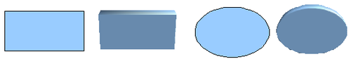
First, draw one of the mutual Draw objects, for example a square/rectangle, circle/ellipse or a text box using the ![]()
![]() or
or ![]() icons on the Drawing toolbar. Next, cull Modify > Convert > To 3D (or right-click on the object and choose Catechumen > To 3D, or click the
icons on the Drawing toolbar. Next, cull Modify > Convert > To 3D (or right-click on the object and choose Catechumen > To 3D, or click the ![]() icon) to produce a 3D object from the 2D surface.
icon) to produce a 3D object from the 2D surface.
The ![]() icon is not ordinarily visible on the Drawing toolbar. To make it visible, select Visible Buttons from the toolbar menu at the right-mitt end of the toolbar and click on the icon to make information technology visible.
icon is not ordinarily visible on the Drawing toolbar. To make it visible, select Visible Buttons from the toolbar menu at the right-mitt end of the toolbar and click on the icon to make information technology visible.
![]()
Extruding 3D objects from 2D surfaces
The procedure by which parallel surfaces are moved to create a 3D object is known as extrusion. In this case the 2D surface is moved forrad "out of" the drawing level. At the same time the object is slightly tilted and central projection turned on then that one can meliorate recognize the object. Draw uses a default value for the extrusion (the body depth) based on the size of the 2d object. The value tin be changed later the extrusion; meet Editing 3D objects.
Variation ii: Body rotation
Cull a common drawing object, for example a (non-blackness) line. So change this into a rotation body. Draw provides 2 methods to do this.
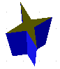
Method 1. Click the icon ![]() in the Drawing toolbar (this icon is also commonly not visible) or choose Modify > Convert > To 3D Rotation object. With this rotation method, the centrality of rotation coincides with the left edge of the enclosing selection rectangle, through the green rectangle handles.
in the Drawing toolbar (this icon is also commonly not visible) or choose Modify > Convert > To 3D Rotation object. With this rotation method, the centrality of rotation coincides with the left edge of the enclosing selection rectangle, through the green rectangle handles.
| | |
| Rotation body created using variation 2.1 | |
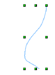
Method 2. Click the icon ![]() on the Effects pulldown menu on the Drawing toolbar. This icon can also be accessed from the Fashion menu, accessible from View > Toolbars > Mode. Notice that this icon lacks the curved red pointer of the stock-still-axis rotation icon.
on the Effects pulldown menu on the Drawing toolbar. This icon can also be accessed from the Fashion menu, accessible from View > Toolbars > Mode. Notice that this icon lacks the curved red pointer of the stock-still-axis rotation icon.
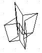
With this method, you tin can modify the location of the rotation axis, which appears every bit a dotted line with two white circular endpoints.
![]()
Rotation body created using variation 2.2
Click ane of the white endpoints and drag it so that the axis moves to the desired position. You lot may need to move both ends to achieve this. The outline shows how the figure will be rotated. When you click on the figure again, the rotation is carried out and the new 3D trunk is produced.
Variation 3: Using ready-made objects
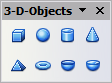
Use the 3D Objects toolbar/pulldown bill of fare. To activate this toolbar, click View > Toolbars > 3D Objects).
![]()
' ' ' The 3D Objects toolbar' ' '
If yous add the icon ![]() to the Drawing toolbar, the 3D Object bar will exist available equally a pulldown bill of fare or as a floating toolbar.
to the Drawing toolbar, the 3D Object bar will exist available equally a pulldown bill of fare or as a floating toolbar.
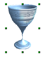
After choosing the type of object, left-click on the starting point and elevate the mouse diagonally until the outline of the object is the size you want.
After releasing the mouse button, the 3D object appears. To modify the summit:width ratio of the object, keep the Shift fundamental pressed while dragging the mouse. Almost of these objects are constructed by rotation. Cubes and spheres are special types of 3D objects that are directly defined in the OOo program code.
3D scenes
Variations one-iii all produce a result known as a 3D scene. If you click on a 3D scene, the status bar text shows 3D scene selected. Such a scene is actually a group of objects.
If you constructed the scene using one of the above methods, it consists of the 3D body equally a single chemical element. 3D scenes can, however, exist extended to include other 3D objects, as described in Combining objects in 3D scenes.
Every bit mentioned in Combining Multiple Objects, you can access private elements of the grouping using Change > Enter group or the context menu. The condition bar text then changes and shows the blazon of each individual chemical element selected, for example Sphere selected or Extrusion object selected.
Producing 3D shapes
Since the release of Version 2.0 of OpenOffice.org, Draw contains a type of cartoon object known every bit a Shape. A special method of extrusion exists for these shapes.
Variation 4: Extrusion of shapes
![]()
![]()
' 'The Bones Shapes toolbar ' '
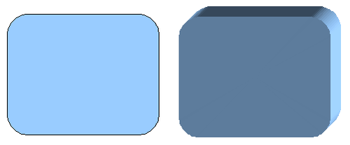
Y'all utilise the Basic Shapes toolbar (or another shape toolbar) to produce 2nd surfaces. Shapes such as cylinders or cubes are technically possible but not very useful, because they produce curiously curved images. If you accept drawn a shape, the terminal icon ![]() on the Drawing toolbar is active. A click on this icon can transform a 2D surface into a 3D object.
on the Drawing toolbar is active. A click on this icon can transform a 2D surface into a 3D object.
![]()
' '3D objects from bones shapes ' '
Extrusion of a shape does not create a new object blazon merely but changes the shape's appearance. All the object'due south properties and settings are retained. You tin can use this button to toggle between a 2D and a 3D view. The actual object properties and settings are non lost in the switching functioning from one view to another.
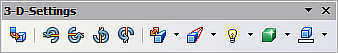
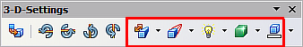
If y'all click on such an object, the 3D-Settings toolbar is available. If this is not automatically opened, switch it on with View > Toolbars > 3D-Settings.
![]()
' '3D-Settings toolbar' '
The commencement icon ![]() corresponds to the icon on the Cartoon toolbar. This icon also works as a toggle switch. Later on changing to 2D, the 3D-Settings toolbar is over again hidden. To change the object back to 3D, y'all must apply the icon
corresponds to the icon on the Cartoon toolbar. This icon also works as a toggle switch. Later on changing to 2D, the 3D-Settings toolbar is over again hidden. To change the object back to 3D, y'all must apply the icon ![]() on the Drawing toolbar.
on the Drawing toolbar.
Variation five: Fontwork
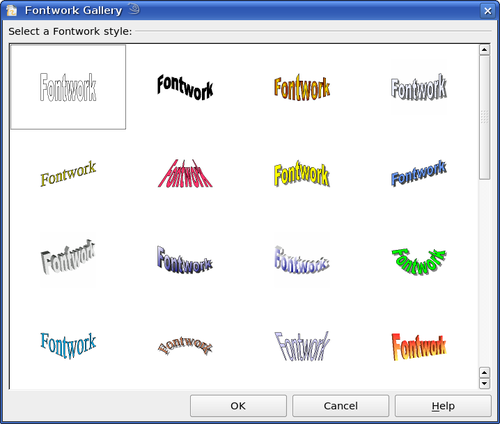
For text you can also use the shapes from the Fontwork Gallery. These produce a similar type of extrusion objects to those from Variation 4.
To open the Fontwork Gallery, use the icon ![]() on the Drawing toolbar.
on the Drawing toolbar.
![]()
' 'Extrusion Shapes from the Fontwork Gallery' '
| | Depict objects of the type "Shape" cannot be viewed with OpenOffice.org Version 1.x. They are but missing from the drawing. If yous save a document with extruded shapes in the older *.sxw format, the shapes will be converted to 3D scenes. |
Editing 3D objects
Rotating 3D objects
Procedure for 3D bodies
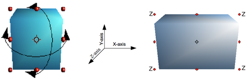
The Rotation command used for 2d objects also works with 3D objects, just due to the boosted axis, in that location are a few differences with the editing of 3D objects. The procedure for selecting the object is identical to that used for a 2nd object.
![]()
' ' 3D object rotation ' '
You lot can rotate the object about each centrality (X,Y,Z). The 10 and Y axes are those parallel to the edges of the drawing layer, while the Z axis comes out of the page. It is not possible to change the centrality orientation.
The three axes are not shown directly, merely the ![]() symbol indicates their intersection point.
symbol indicates their intersection point.
| You lot want to ... | You must ... |
|---|---|
| ... rotate the object virtually the Ten or Y axis. | ... put the mouse cursor over the object. With the left mouse cardinal pressed you can now rotate the object every bit you wish. Moving one of the red points at the middle of an edge allows yous to rotate the object well-nigh merely one centrality. Note that the cursor initially has the shape for a (2D) shearing movement but pressing the mouse button changes it to a rotation cursor. |
| ... rotate the object nearly the Z axis. | ... movement the handle on one of the corner points with the left mouse button pressed. Rotation near the Z axis is independent of the setting of the rotation angle in the dialog Position and Size. |
| ... motion the axis intersection point. | ... simply drag the Symbol |
These rotations can exist carried out on a 3D scene equally a whole or on private objects inside a 3D scene.
Procedure for 3D shapes
Objects produced using variations 4 and 5 (meet above) can only be rotated about the Z axis when using the iii methods described in the previous department. This rotation is carried out on the underlying 2D object. It is also possible to rotate the 3D object in the aforementioned manner equally with a 2D object using Format > Position and Size > Rotation (shortcut fundamental for Position and Size is F4) and specifying the pin signal location and the number of degrees of rotation desired.
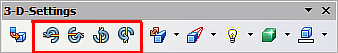
Shape objects have their own procedure for rotation about the X and Y axes. If you have activated the 3D-Settings toolbar (nether View > Toolbars ), this becomes active when y'all select the 3D object; icons 2 to 5 on this toolbar rotate the object in 5 caste increments about the X and Y axes.
![]()
3D-Settings toolbar with rotation icons indicated
3D settings for 3D bodies
3D Effects dialog — general buttons
The 3D Effects dialog offers a wide range of possible settings for 3D objects produced with variations one to iii (encounter previous sections). To open the dialog, right-click on the object and choose 3D Effects from the pop-up carte du jour. You tin also activate a 3D Effects icon ![]() on the Standard toolbar or add it to another toolbar using Customize Toolbar > Add > Category Options > 3D Effects.
on the Standard toolbar or add it to another toolbar using Customize Toolbar > Add > Category Options > 3D Effects.
The dialog can be docked in a similar mode to the Navigator or Template windows.
The possible settings are arranged in diverse thematic categories on carve up pages, accessible through the buttons at the peak of the window, which act in a similar way to tabs. To apply the settings you take altered, click the Assign button ![]() . This applies all the changes you have made to the object on the other pages of the dialog as well as the current one.
. This applies all the changes you have made to the object on the other pages of the dialog as well as the current one.
![]()
![]()
Upper role of the 3D Effects dialog
| | Only the selected effects are assigned to the object. There is no object conversion; thus a cylinder cannot exist transformed into a band through the application of a 3D issue. All the same, it is possible to change the appearance to a wooden or metal body. Past the assignment of a 3D effect, second objects are transformed into 3D objects. |
In gild for the Effects dialog to have over all the current properties of the object, you must click the ![]() button. If you deactivate this push button before yous leave an object and click on it once more when you open the Effects dialog for another object, the settings are carried over from the first object to the second object. You can employ this to transfer favorite settings from i object to some other, every bit all the settings are brought over to the new object. In normal use, still, the icon should be left activated.
button. If you deactivate this push button before yous leave an object and click on it once more when you open the Effects dialog for another object, the settings are carried over from the first object to the second object. You can employ this to transfer favorite settings from i object to some other, every bit all the settings are brought over to the new object. In normal use, still, the icon should be left activated.
At the bottom left of the dialog is another row of buttons, which are available on each page.
![]()
![]()
Buttons for geometric transformations
The first ii buttons correspond to the menu commands Alter > Catechumen > To 3D / To 3D Rotation Object. When the Effects dialog for a 3D object is called upward, these buttons are inactive. The third icon switches on or off a perspective view of the object.
With a central projection parallel edges are shown as meeting at some common point in the altitude, equally shown on the push symbol. Parallel projection retains all parallel edges as parallel, every bit is oft used to produce oblique figures in schoolhouse. The switching procedure is carried out on the entire 3D scene.
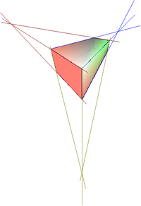
With cardinal projection, Depict creates the object with three vanishing points. The parameters for primal projection are set up (indirectly) through the camera settings on the Shading dialog folio.
![]()
Figure shown using cardinal projection. For clarity the projection lines have been added.
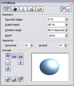
3D Effects - Geometry
On the Geometry page, you can brand changes to the geometry of a 3D object. This folio is opened with the Geometry button ![]() in the upper part of the 3D Furnishings dialog.
in the upper part of the 3D Furnishings dialog.
![]()
Geometry folio
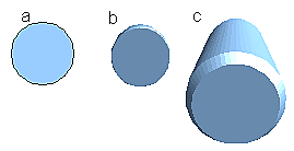
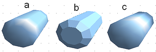
In the get-go example, the depth (length) of a torso is to exist changed. This is possible only if you lot created information technology through extrusion. To illustrate: draw a circle and catechumen information technology according to Variation one into a 3D object (a apartment cylinder); run across Figures a and b beneath.
If necessary, select the cylinder, open up the 3D Effects dialog, make sure the Geometry page is active, change the parameter Depth to 3.5cm and click on the Assign icon ![]() . The cylinder should now resemble the figure in Effigy c.
. The cylinder should now resemble the figure in Effigy c.
![]()
Conversion by extrusion of a 2nd object (a) into a 3D object (b) and so changing its depth (c)
This parameter has no outcome on a rotation torso or on set-made 3D objects, although the input field remains active.
With the Rounding parameter you tin can specify how strongly the edges of the 3D object are rounded. Select (if necessary) the lengthened cylinder over again and utilize the 3D Furnishings dialog to alter the rounding to 30%. The cylinder should now resemble that beneath.
![]()
Edge rounding of 10% (a) and 30% (b)
This parameter also has interesting effects when you convert text into a 3D object.
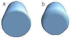
The Scaled Depth parameter sets the size ratio of the front to the dorsum for a 3D object produced by extrusion. The front side of such an object always protrudes out from the original surface; the rear side is the original surface of the 2d object (that is, the second exit surface) even if the object has been rotated in the meantime.
By default the scaling is gear up to 100%, which results in both surfaces existence scaled by the same corporeality. If yous prepare this scaling to fifty% the cylinder becomes a truncated cone.
![]()
Cylinder with l% scaling
The diameter of the front side is 50% that of the rear side. It is also possible to create the reverse issue, with the rear side smaller than the forepart, by using a scaling depth greater than 100%.
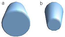
With rotation bodies this parameter influences the width of the surface parallel to the centrality of rotation. At the end of the rotation the surface width of the effigy is given by the scaling depth. The altitude to the rotation axis remains unchanged. In the figure below, a line is rotated to create a 3D object with a scaling depth effigy of 0%.
![]()
Scaling depth of a rotation body
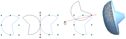
The Rotation Bending parameter is just available for rotation bodies. With this parameter you can create a segment of a complete rotation body past choosing an bending less than 360 degrees.
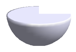
![]()
Hemisphere with a rotation angle of 270°
The Horizontal and Vertical Segments parameters define the number of segments out of which Draw builds spheres and rotation objects[ane]. For rotation objects, the horizontal segments are more important. The vertical segments influence the degree of border rounding.
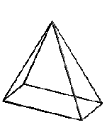
In this figure, the left sphere is made up of 10 horizontal and vertical segments while the right sphere has 25 segments. More segments give a smoother surface, just it volition accept longer to generate the figure on the screen. By default, spheres and hemispheres are synthetic with 24 segments. For a square pyramid you demand iv horizontal segments.
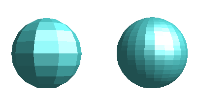
![]()
Sphere from 10 segments (left) and 25 segments (right)
These are properties belonging to individual objects. If yous use the setting for segments on a 3D scene, all the objects contained in the scene are modified accordingly.
If you extrude an unfilled circle or intersecting lines with a filling the issue may not exist what you expect. In this case the Double-Sided ![]() tool, on the lower part of the dialog page, may be able to help. It changes the line properties of an object from invisible to continuous and so enables all edges to be seen. Otherwise information technology may happen that some surfaces receive no filling. For lines without filling the effect is switched on past default and cannot be switched off. This is also a holding of single objects.
tool, on the lower part of the dialog page, may be able to help. It changes the line properties of an object from invisible to continuous and so enables all edges to be seen. Otherwise information technology may happen that some surfaces receive no filling. For lines without filling the effect is switched on past default and cannot be switched off. This is also a holding of single objects.
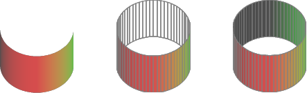
![]()
Left: without "Double-Sided" Heart: with continuous lines just without "Double-Sided" Correct: with "Double-Sided"
Use the buttons in the section Normals to modify the normals of a 3D object.
A Normal is a straight line which is perpendicular to the surface of an object (in the aforementioned fashion that a vector, starting from an inner point and extending outwards, is at right angles to the surface of the object at the point where it exits). The figure below shows some normals extending outwards from a sphere made up of 10 segments.
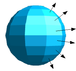
![]()
Normals (vectors) of a 3D sphere with x segments
Using normals, the display of the object surface and the variation in colors, textures and lighting tin can be controlled, influencing direct how the surface of the object is rendered.
The start 3 icons in the Geometry dialog (shown at the beginning of this paragraph) work every bit "either-or" switches. Only 1 of the effects can exist active at a given time; an effect can exist switched off by clicking on i of the other icons.
The settings vest to private objects, not scenes; every object can have its own setting. The rest of the icons are normal toggle "on-off" switches. The following effects are available:
![]()
Cylinder with 10 segments a= Object-specific b=Flat, c=Spherical
The post-obit tabular array shows the linkage between double-sided illumination and inverted normals.
3D Effects - Shading
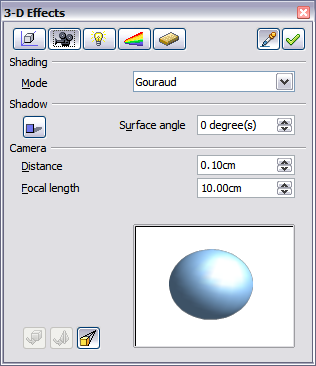
The Shading page offers functions for shading the object surface, adding shadows and choosing photographic camera settings.
Shading is a rendering method involving a consideration of lighting ratios, which is used to produce curved 3D surfaces. The surfaces are broken down into modest triangular segments. Describe offers iii methods to produce this effect: Flat, Phong and Gouraud. The setting selected applies to all objects in the 3D scene.
![]()
Shading page
- Flat is the fastest and simplest method. For every individual segment a special color tone is determined, based on the lighting ratio and the direction of the segment area. This tone is used for the whole expanse of the segment. The segmentation is clearly visible.
- Phong is the virtually fourth dimension-consuming method. With this method, for each pixel the associated normal is determined by interpolation, based on the normals of the segment edges. This causes the segment expanse to announced curved and the segment intersections are no longer visible.
- Gouraud is a relatively quick method. It determines the color value for the segment corners and calculates the color value for every pixel through linear interpolation. The segment edges are nonetheless recognizable, but importantly are less so than with the apartment method. The Gouraud method considers only calorie-free reflection on diffuse, reflecting surfaces (dispersal).

![]()
Flat, Phong and Gouraud shading
In the effigy shown higher up the left sphere was rendered with flat shading, the middle with Phong and the right with Gouraud. The quality of the apartment method is conspicuously inferior to the other two. The deviation betwixt Phong and Gouraud is small. With the Gouraud method the segments can exist very faintly seen and rendered objects accept a slightly less "shine" than with the Phong method.
All 3 methods function at the pixel level and as such, shadowing and mirroring inside the 3D scene is non possible in the fashion that ray tracing methods let.
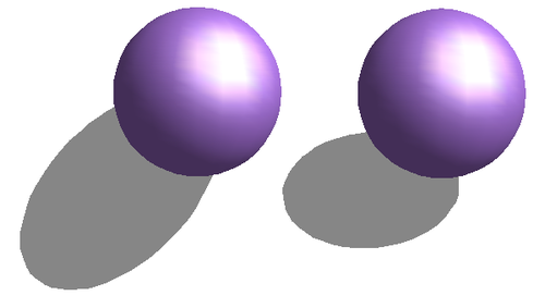
With the the Shadow button ![]() you tin can provide a 3D object with a shadow. By changing the Surface angle you tin can influence the form of the shadow. The left sphere below has a surface bending of 0° (the paper represents a perpendicular surface backside the object) while the correct sphere has a surface bending of 45°. With 90° the paper would be directly nether the object.
you tin can provide a 3D object with a shadow. By changing the Surface angle you tin can influence the form of the shadow. The left sphere below has a surface bending of 0° (the paper represents a perpendicular surface backside the object) while the correct sphere has a surface bending of 45°. With 90° the paper would be directly nether the object.
![]()
Shadows using unlike surface angles
The shape and size of the the shadow are too influenced by the lighting properties. These tin can exist adjusted on the Illumination page of the dialog. Multiple light sources for shadows are not withal supported. The shadow properties can be set for individual objects in a drawing simply where objects form part of a 3D scene, the shadow produced is that of the entire scene.
Information technology is possible to set the shadow property for single objects using the Area holding. The shadow is then shown with the colour selected in the shadow dialog, merely once again the representation of the lighting of the scene determines the end outcome of the entire scene. In this way, colored shadows, with different distances to the object, and different color and transparency effects tin can be created.
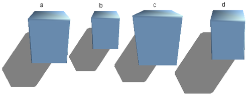
In the Photographic camera field of the shading dialog the settings of the virtual camera tin can be changed. These settings relate only to the view in central projection and utilize to the entire 3D scene. The Distance parameter is used to adjust the spacing betwixt the camera and scene. The default value for an extruded body is equal to the depth or length of the trunk. With equal length edges front and rear, the result at large distances is quite modest. The standard value of Focal length is 10cm. It has the same significance as with a real photographic camera. Larger focal lengths simulate a telephoto lens, smaller ones a wide-bending lens. The outcome that changes in the camera settings have on an object are shown below.
![]()
Effect of camera settings
Pic a shows a 3D object with the standard settings. The individual changes are listed in the following table.
| | | | | |
| Distance: | | | | |
| Focal length: | | | | |
3D Effects - Illumination
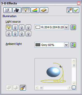
On the Illumination page y'all define how a 3D object is lit. The settings apply to all objects in a scene.
![]()
Illumination (lighting) page
You can lite a scene with a maximum of eight private Light sources at the same fourth dimension. For each of these sources the light color and position relative to the scene can be set. The low-cal sources are represented by eight pocket-size calorie-free bulbs. When you select this folio, the first bulb "lights upwards" ![]() . At least i light source must be active; otherwise, the rendering and shading functions cannot function correctly.
. At least i light source must be active; otherwise, the rendering and shading functions cannot function correctly.
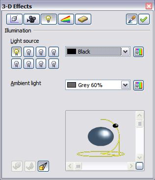
Each symbol functions like a multi-role press switch. With the offset mouse click the bulb is selected and with the 2d click the settings style for this light source is activated. A third click deactivates the light source.
![]()
Aligning of low-cal source
In the selection list side by side to the symbols you can choose the color of the active light source. If desired, click the ![]() button to open a color palette dialog, where you can define your ain color and likewise adjust the brightness. For the first lite source, it is best to retain the neutral color value (default is white); with several calorie-free sources it is advisable to reduce the effulgence.
button to open a color palette dialog, where you can define your ain color and likewise adjust the brightness. For the first lite source, it is best to retain the neutral color value (default is white); with several calorie-free sources it is advisable to reduce the effulgence.
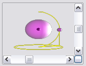
In the lower right corner of the menu the low-cal source location and orientation is depicted. With the vertical slider bar you tin can adjust the lighting angle; with the horizontal bar the light is rotated nearly the object. Alternatively you can click on the light point and elevate the signal every bit yous please. Click on the small foursquare in the bottom right (circled) to change the preview image from a sphere to a cube.
![]()
Moving the light source
To apply the changed settings to the selected object, click on the the Assign button ![]() .
.
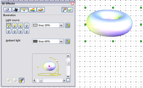
The use of additional light sources can result in some interesting effects.
![]()
Lighting with three independent lite sources
In Effigy 31 the band has the lighting settings from Figure 30 with the standard colour white. In add-on it was lit with magenta, and also from the left underside with yellow. The number and position of the light sources is shown in the window at the lower right. The iii calorie-free sources in use can be recognized past the "lit" symbols ![]() .
.
To see the consequence of a particular lighting upshot you can also temporarily turn it off. With an object selected, clicking on a "lit" symbol turns it off ![]() . This new setting must and then be applied (assigned) to the scene. With a further mouse click on the lite source the effect can be switched back on and and then re-assigned.
. This new setting must and then be applied (assigned) to the scene. With a further mouse click on the lite source the effect can be switched back on and and then re-assigned.
You tin can also change the settings for the Ambient lighting. The option of properties (lighting color, brightness, then on) is carried out in aforementioned way as for light sources.
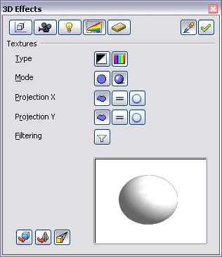
3D Effects - Textures
Textures are raster graphics (bitmaps) which tin be used as an object belongings for the surface of an object. Every object in a 3D scene can have its own texture.
You lot tin set a raster graphic as a texture for a 3D object in the same way every bit for a second object (Format > Area > Bitmaps or right-click on the object > Area > Bitmaps) — as is the case for Gradient and Hatching. More details are found in Irresolute Object Attributes.
If the Fill setting on the Area dialog is Colour, then the Texture page is inactive. Change it to Bitmap to activate the Texture page for 3D objects. If the texture is not tiled or stretched and is smaller than the object, and then the residuum of the area volition have the color of the Object color belongings on the Material page.
![]()
Textures page
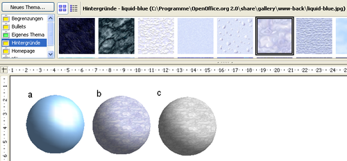
In the first row of the page are two switches (Type) with which y'all can choose between black and white or color for the texture.
![]()
a - standard color setting, b - texture (color), c - texture (blackness and white)
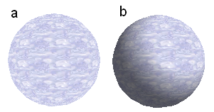
With the two switches in the row Mode you lot can control whether the texture of the selected objects is rendered with light and shadows (Switch 2) or non (Switch 1). By means of advisable lighting and shading adjustments, the graphic object is more realistically rendered.
![]()
Texture without (a) and with (b) lighting and shadow effects
Project 10 / Y
With one of the 3 buttons you can determine how the texture for this coordinate centrality should be projected onto the object. The default setting, Object specific, in full general gives the all-time result. Examples of the use of each push button are shown below.
For a rotation body, the turning axis is the Z axis and the wrapping is the 10 management; for an extrusion body, the extrusion direction is the Z centrality and the extruded surface is the X direction. Depending on how the object was produced, unlike positions of the texture result.
 Area make full without tiling, with adjustments | Projection X | Projection X | Projection X |
| Projection Y |  |  |  |
| Projection Y (Difference is small) |  |   |  |
| Cylinder as a rotation body | |||
| Area fill without tiling, with adjustments | Projection Ten | Projection Ten | Projection X |
| Projection Y | 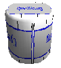 | 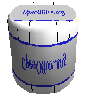 | 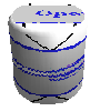 |
| Projection Y (Difference is small) | 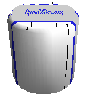 | 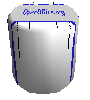  | 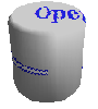 |
| Cylinder as an extrusion object | |||
The Filter push ![]() switches on and off a soft-focus filter. It can frequently remove slight faults and errors in the texture.
switches on and off a soft-focus filter. It can frequently remove slight faults and errors in the texture.
3D Effects - Material
On this page you can assign the appearance of different materials to the 3D object.
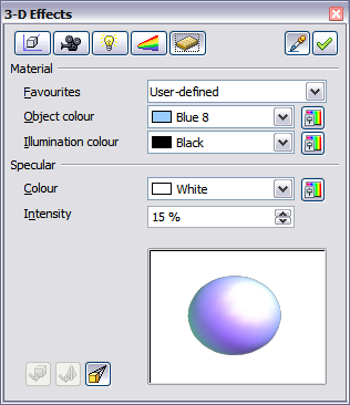
![]()
Material menu
In the option list under Favorites are the most commonly used materials.
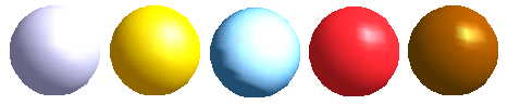
![]()
The favorites (from left to correct): Metallic, Gold, Chrome, Plastic and Wood
With the individual color parameters, boosted furnishings can exist produced. The meaning of these parameters corresponds to those on the Illumination dialog page.
Materials and textures can be combined with 1 another. Settings only simulate materials and it is sometimes a affair of trial and mistake to achieve the desired result.
| | Do not utilize besides high a effulgence value for individual colors. These are all additive and it is easy to stop up with a totally white "colored" area. |
| The Illumination color brightens those parts of the object which lie in shadow making the trunk seem more illuminated. When textures are used besides, the Illumination colour is combined with the white colour part of the texture. On the left the object has a black Illumination color, on the right bright greenish. |  |  |
| The Specular color simulates the reflecting capacity of the surface. The position of the illuminated point is adamant by the setting of the first light source. Left: Set the Specular color the same as the object color and the illumination betoken intensity to a depression value, in order to give the impression of a matt trunk. Right: Prepare the Illumination signal color the aforementioned every bit the low-cal source colour, in order to give a shiny appearance to the object surface. | 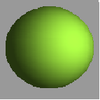 | 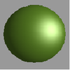 |
Metal surfaces and glass are not and so well false, because the impression of these materials is produced through reflection. Such simulation cannot (at the moment) exist calculated by OpenOffice.org.
3D settings for 3D shapes
3D shapes are handled quite differently from objects in 3D scenes. The appearance of a shape object is changed using the 3D-Settings toolbar. The 3D Effects dialog described above should non be used for shape objects as it volition not give the correct formatting results.
![]()
3D-Settings toolbar, indicating icons for formatting 3D shapes
If you have used information technology in error, you can remove the incorrect formatting with Format > Default Formatting.
With the buttons on this toolbar you tin can adjust the extrusion depth and perspective, lighting and textile properties as well every bit the extrusion colour. In that location are tear-off bars, which you open by clicking on the small black triangle. The purpose of each private button is described by its tool tip. Yous do not need to assign the issue of whatever of the functions to the object as you do with the 3D Effects dialog used with 3D scenes; every action is immediately applied and you tin can see its consequence on the object in the main Describe window.
| | The program may sometimes seem to generate the wrong formatting with shape objects. The exact cause is non known, just you tin undo the action with Format > Default Formatting. One reason for bad formatting can be that you have used a function from the 3D Result dialog on a 3D shape. |
Here are some examples of formatting of 3D shapes:
 |  | Depth left: 0.3cm (user defined) right: 1cm (choice) |
 |   | Direction The examples prove "columns" at correct angles to the drawing surface. left: five cm depth, Parallel project Heart: 10 cm depth, Perspective right: Infinity, Perspective |
 |   | Illumination The light color cannot be changed, the effulgence can exist changed only in iii levels, and some furnishings may not exist totally correctly rendered. left: from left under, dim middle: from left under, bright right: from right under, normal |
 |  | Surface Simply four born variations are possible. At nowadays just Wireframe and Matt are correctly rendered. left: Wireframecorrect: Matt You can also cull a gradient, hatching, or bitmap for the surface; these are but practical to the extruded surface — the sides remain in the color of the object. |
 |  | 3D Color Here you tin choose the colour of the sides of the extruded surface. The symbol shows the color of the most recently chosen shape object. |
Combining objects in 3D scenes
3D objects produced by extrusion or rotation are shown in the condition bar as a 3D scene. You lot can group together several of these objects. Other object types cannot be so grouped. Management of the grouping is carried out in the same mode as described in other parts of this guide (Modify > Enter Group, or Modify > Exit Group), see also Grouping objects.
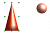
Every bit an instance, nosotros will produce a game piece.
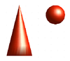 | First produce both objects independently of each other. The subsequent combination is made easier if you use parallel project and rotate the objects into an upright, straight position. |
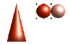
 | Click on the sphere and use Edit > Re-create to take over the scene and put the sphere on the clipboard. If y'all are certain that you lot do non need the original anymore you lot can use Edit > Cut. In any case motility the sphere a little to the side. |
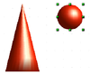
 | Click at present on the cone. The status bar will show 3D Scene selected. Right-click and enter the group. You lot will see that, as usual, elements that do not vest to the grouping are less vivid. Use Edit > Paste. Now the objects (not the whole scene) from the clipboard are pasted into this scene. |
 | The original position of the sphere now contains a new sphere that belongs to the scene. This new sphere tin can be dragged over to the cone. Get out the group after moving the sphere. |
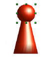 | Notice that combining 3D objects results in them being more or less "fused" together — there is no stacking or layering every bit with 2D objects. Adjust the position of the objects as you wish. You cannot arrange objects in front or behind others, as with 2D objects, just can but move them parallel to the drawing plane. |
 | Enter the group again and adjust the objects. The condition bar indicates which object is marked. Use the Tab key to change from 1 object to the side by side in the grouping, if it is not possible to practise then with the mouse. Exit the group. |
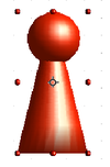
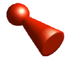 |  Now you can rotate the entire 3D scene and view your game slice from all sides. Now you can rotate the entire 3D scene and view your game slice from all sides. |
Examples for your own experiments
All examples use objects in 3D scenes.
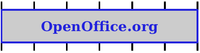
  | Extruding a 2D object with text generates letters as carve up objects and they take a larger extrusion depth than the groundwork. |
  | 3D objects of the Shape type can be rendered as wireframe models. This effect can be produced in other 3D objects by setting the Area fill up to None and the line manner to Continuous. |
  | If y'all select several 2D objects — without grouping them — and extrude the choice, they are transformed, according to their stacking social club, with different extrusion depths. The object previously on meridian volition be uppermost on the extruded object. |
  | For 2D objects use Alter > Shapes > Merge/Subtract/Intersect to produce circuitous objects. The resulting figures can be also extruded, rotated so on. |
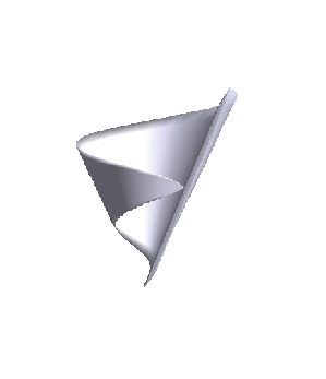
 | Rotation of lines produces concave bodies. Use a bright line color. With a high number of vertical segments, the transition to the ground is relatively abrupt-edged. Call back to switch on two-sided illumination. |
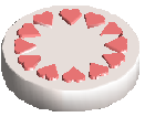
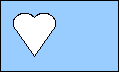
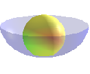 | The transparency of the platter is adjusted in the surface backdrop of the body. The best effect is obtained simply when the transparent torso is combined with other objects. The colour shadow of the fruit is produced past the use of multiple calorie-free sources — they are not "real" and practice not rotate and change as the scene is rotated. |
- ↑ To reduce both calculation fourth dimension and data storage, circles are ofttimes constructed equally regular polygons. If y'all cut a sphere or cylinder of 10 segments through the middle you finish up with a xx-cornered cutting section (ten-cornered for a hemisphere).
daddarioeingthishe.blogspot.com
Source: https://wiki.openoffice.org/wiki/Documentation/OOo3_User_Guides/Draw_Guide/Working_with_3D_Objects#:~:text=Use%20the%203D%20Objects%20toolbar,%3E%20Toolbars%20%3E%203D%20Objects).&text=to%20the%20Drawing%20toolbar%2C%20the,or%20as%20a%20floating%20toolbar.
0 Response to "where is the 3d objects toolbar in open office draw"
Post a Comment